Introduction
I wanted a keyboard for an SRAM project I have been working on. The keyboard was an interesting enough design I felt it warranted its own post. My needs for the keyboard were a minimum of 16 keys - each representing a hex character. I ultimately went with an 18-key keyboard as I had 18 6mm switches handy and it fit nicely on the protoboard.
Design
Disclaimer: I won't go into detail on how a keyboard matrix works or how I²C works, as that is beyond the scope of this post. If you're interested or need an introduction/refresher, Dave Driblin has a classic (and in-depth) reference on keyboard matrices. (Archived)
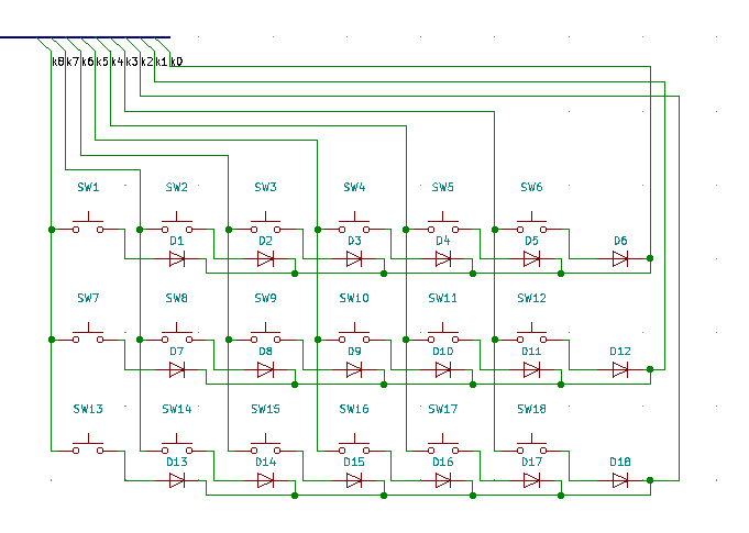
I decided to go with 3 rows of 6 columns, which meant I'd need 9 pins of the MCU I was using. In this case that MCU was an off-branded version of the SparkFun Pro Mini. For each key I also added a 1N4148 signal diode to handle any ghosting.

BOM
For the keyboard alone (without the Pro Mini) the bill of materials is as follows:
| Label | Component | Quantity |
|---|---|---|
| SW1-S18 | 6mm Push Button | 18 |
| DW1-D18 | 1N4148 | 18 |
Code
The code is fairly simple. On the high-level it transmits a 3-byte array via I²C. Each of the most significant 6 bits of the 3 bytes represents a key. See the various comments in the code for more specific explanations. For this code I'm using digital pins 2-4 on the Pro Micro for the rows of the matrix and digital pins 5-10 for the columns. The analog pins A4 and A5 on the Pro Micro are used for I²C SDA and SCL, respectively.
#include <Wire.h>

byte keys[3] = { 0 };

void setup() {
  Wire.begin(0x5C);  // Set the I²C address
  Wire.onRequest(sendData);  // Set the handler function
}

void loop() {
}

void sendData() {
  readKeys();

  // Transmit each byte one at a time
  for (int i = 0; i < 3; i++) {
    Wire.write(keys[i]);
  }
}

void readKeys() {
  for (int i = 0; i < 3; i++) {
    pinMode(i + 2, OUTPUT);  // Enable the current row
    digitalWrite(i + 2, LOW);
    keys[i] = 0;  // Clear the current row's byte
    for (int j = 0; j < 6; j++) {
      pinMode(j + 5, INPUT_PULLUP);  // Enable the current column
      keys[i] |= !digitalRead(j + 5) << (7 - j);  // Read the current column
      pinMode(j + 5, INPUT);  // Disable the current column
    }
    pinMode(i + 2, INPUT);  // Disable the current row
  }
}
Build
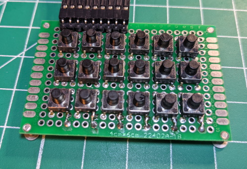
The first prototype build went surprisingly well. After soldering the first row I discovered a better technique for placement of the other two rows' diodes. I also added some screws for feet to make pressing the buttons a bit easier.

Custom PCB
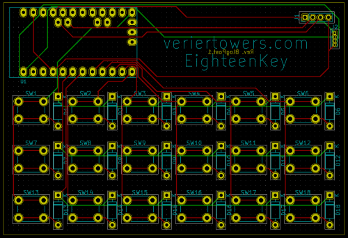
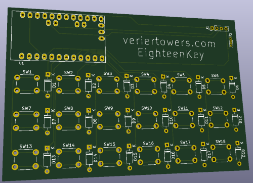
For this project I decided to learn KiCAD. I laid out the schematic above in KiKAD and also designed the PCB below. I added a header for programming the Pro Mini as well. All files are available under deliverables.


Deliverables
dustin
2021-05-20